@activities 1
Inputs & Outputs with Microbit
basic.forever(function () {

})
Introduction
Introduction step @unplugged
 You will learn how to use certain input sensors and outputs with your micro:bit
To get started we will connect and test your micro:bit
Activity 1 - Connect & Test Microbit
Step 1 Connecting the microbit
Plug in your microbit and connect! ———————————- Need to know how to connect your microbit to your computer? Watch this video
Step 2 @fullscreen
Test your microbit without Grove
————————————
Place the ||basic:show leds|| block in the ||basic:forever|| block and draw a pattern.
basic.forever(function () {
    basic.showLeds(`
        # . # . #
        . # # # .
        # # # # #
        . # # # .
        # . # . #
        `)
})
Step 3 - Upload the code
|Download| your code
————————-
Need help connecting?
Activity 2 - Control a light
Step 1 - Collect Parts @unplugged
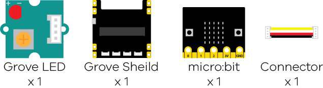
Control a light ============= In this activity you will learn how to turn an LED on and off
Collect the parts you will need;
Step 2 - Connect Wires
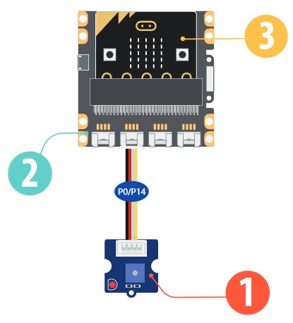
Physical Connection ——————-
- Plug the microbit into the Shield
- Plug the LED into Pin 0
Step 3 - Program
Coding: Turning the light On
———————————
Place an ||input:on Button A Pressed|| then add a ||pins:digital Write Pin|| block (Under Advanced)
Change the 0 to a 1 (This will make the light turn on)
input.onButtonPressed(Button.A, function () {
    pins.digitalWritePin(DigitalPin.P0, 1)
})
1 = On
0 = Off
Step 4 - Program Continued
Coding: Turning the light Off
———————————
Place another ||input:on Button A Pressed|| and change it to when ‘B’ is onButtonPressed
Add another ||pins:digital write pin||
input.onButtonPressed(Button.A, function () {
    pins.digitalWritePin(DigitalPin.P0, 1)
})
input.onButtonPressed(Button.B, function () {
    pins.digitalWritePin(DigitalPin.P0, 0)
})
1 = On
0 = Off
Step 5 - Download Program
Download & Test
——————–
Click |Download| to transfer your code and press button A and B to see if the works
Activity 3 - Sense the light level
Step 1 - Collect Parts @unplugged
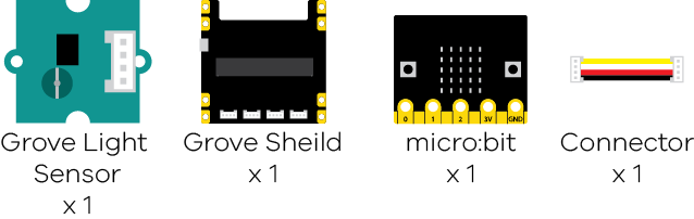
Sense the light level ============= In this activity you will learn how to sense the amount of light or brightness
Collect the parts you will need;
Step 2 - Connect Wires
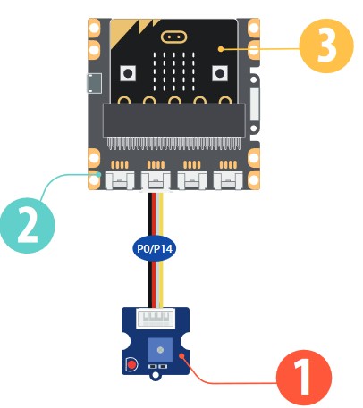
Physical Connection ——————-
- Plug the microbit into the Shield
- Plug the Light Sensor into Pin 0
Step 3 - Program
Coding: Clean Up
—————–
For each new activity you will need to remove all previous blocks.
Delete all previous blocks from the workspace
Step 4 - Program
Coding: Preparing the micro:bit graph
——————
Place a ||basic:forever|| block and insert a ||led:plot bar graph of ... up to|| block
Change the ||led:up to|| number from ‘0’ to ‘1023’
basic.forever(function () {
    led.plotBarGraph(
    0,
    1023
    )
})
‘1023’ is the range of the sensor
Step 5 - Program Continued
Coding: Read & graph the light level
——————————-
Place a ||pins:analog read|| into the ||led:plot bar graph of|| field
basic.forever(function () {
    led.plotBarGraph(
    pins.analogReadPin(AnalogPin.P0),
    1023
    )
})
Step 6 - Program Continued
Coding: Give the micro:bit some time to do its thing
—————————————————–
To give the sensor enough time to work, place a ||basic:pause|| after the ||led:plot bar graph of... up to..||
Change the value of the pause to 10ms (_Hint_: you can type)
basic.forever(function () {
    led.plotBarGraph(
    pins.analogReadPin(AnalogPin.P0),
    1023
    )
    basic.pause(10)
})
The pause gives just enough time for the sensor to work correctly
Step 7 - Download Program
Download & Test
——————–
Click |Download| to transfer your code
As you cover the light sensor the microbit graph should go up/down
Activity 4 - Rotary Encoder
Step 1 - Collect Parts @unplugged
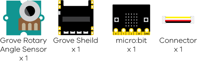
Turn to Change ============= In this activity you will learn how to use the rotary angle sensor
Collect the parts you will need;
Step 2 - Connect Wires
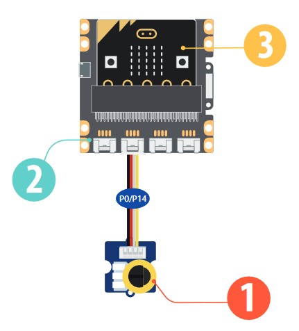
Physical Connection ——————-
- Plug the microbit into the Shield
- Plug the Rotary Angle Sensor into Pin 0
Step 3 - Program
Coding: Clean Up
—————–
Remove all previous coding blocks from the workspace
Step 4 - Program
Coding: Preparing the micro:bit graph again
——————
Place a ||basic:forever|| block and insert a ||led:plot bar graph of ... up to|| block
Change the ||led:up to|| number from ‘0’ to ‘1023’
basic.forever(function () {
    led.plotBarGraph(
    0,
    1023
    )
})
‘1023’ is the range of the sensor
Step 5 - Program Continued
Coding: Connect the potentiometer to the microbit
——————————-
Place a ||pins:analog read|| into the ||led:plot bar graph of|| field
basic.forever(function () {
    led.plotBarGraph(
    pins.analogReadPin(AnalogPin.P0),
    1023
    )
})
Step 6 - Program Continued
Coding: Give the micro:bit some time to do its thing
—————————————————–
To give the sensor enough time to work, place a ||basic:pause|| after the ||led:plot bar graph of... up to..||
Change the value of the pause to 100ms (_Hint_: you can type)
basic.forever(function () {
    led.plotBarGraph(
    pins.analogReadPin(AnalogPin.P0),
    1023
    )
    basic.pause(100)
})
The pause gives just enough time for the sensor to work correctly
Step 7 - Download Program
Download & Test
——————–
Click |Download| to transfer your code
As you turn the rotary angle sensor, the microbit graph should go up/down
Activity 5 - Speaker
Step 1 - Collect Parts @unplugged
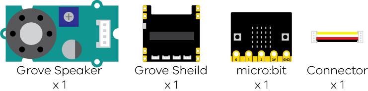
Music Time ============= In this activity you will learn how to use the external speaker
Collect the parts you will need;
Step 2 - Connect Wires
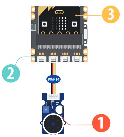
Physical Connection ——————-
- Plug the microbit into the Shield
- Plug the Speaker into Pin 0
Step 3 - Program
Coding: Clean Up
—————–
Last reminder: On a new activity
Remove all previous coding blocks from the workspace
Step 4 - Program
Coding: Playing Tones
——————
Place a ||input:on button A pressed|| block and insert a ||music:play tone 'middle C' for '1 beat'|| block
input.onButtonPressed(Button.A, function () {
    music.playTone(262, music.beat(BeatFraction.Whole))
})
Try some other notes
Step 5 - Program
Coding: Playing Melodys
——————
Place a ||input:on button A pressed|| block and change ‘A’ to ‘B’
Insert a ||music:play melody|| block. Create a melody
input.onButtonPressed(Button.A, function () {
    music.playTone(262, music.beat(BeatFraction.Whole))
})
input.onButtonPressed(Button.B, function () {
    music.playMelody("- - - - - - - - ", 120)
})
Experiment with different notes and bpm
Step 6 - Download Program
Download & Test
——————–
Click |Download| to transfer your code
When you press A the tone will play, when you press B the melody will play
Activity 6 - Gestures
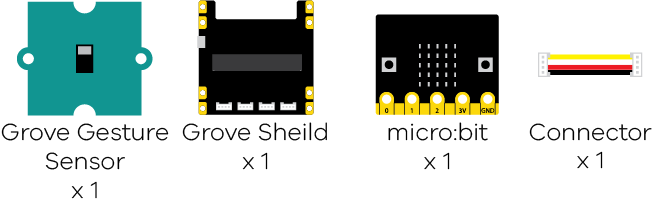
Step 1 - Collect Parts @unplugged
Left or Right Gestures ============= In this activity you will learn how to use the external speaker
Collect the parts you will need;
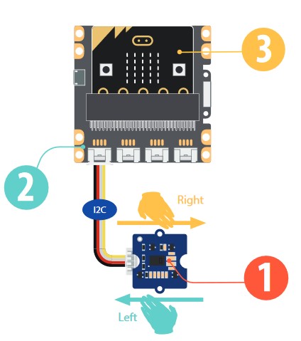
Step 2 - Connect Wires
Physical Connection ——————-
- Plug the microbit into the Shield
- Plug the Gesture Sensor into the I2C Pin
Step 3 - Program
Coding: Gesture Input
——————
Place a ||grove:on gesture|| block and change the gesture to ||grove:Right||
grove.onGesture(GroveGesture.Right, function () {
})
Step 4 - Program
Coding: Action from Gesture Input
——————
Place a ||basic:show string|| block inside the ||grove:on gesture|| and change the word from “Hello” to “R”
grove.onGesture(GroveGesture.Right, function () {
    basic.showString("R")
})
Step 5 - Program
Coding: Other Gestures
——————
Place a new ||grove:on gesture|| block and change the gesture to ||grove:Left||
Insert a ||basic:show string|| and change the word to “L”
grove.onGesture(GroveGesture.Right, function () {
    basic.showString("R")
})
grove.onGesture(GroveGesture.Left, function () {
    basic.showString("L")
})
This will now sense both directions
Step 6 - Download Program
Download & Test
——————–
Click |Download| to transfer your code
When you move your hand Right, the screen will say “R”, when you move your hand Left, the screen will say “L”
Activity 7 - Counter
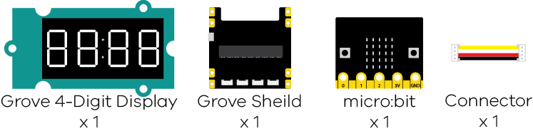
Step 1 - Collect Parts @unplugged
Counting Counter ============= In this activity you will learn how to use 4-digit display
Collect the parts you will need;
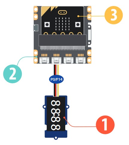
Step 2 - Connect Wires
Physical Connection ——————-
- Plug the microbit into the Shield
- Plug the 4Digit Display into the P0 pin
Step 3 - Program
Coding: Setup the display
——————
Place a ||grove:Set 4Digit to Display|| block inside a ||basic:On Start||
Set the pins to ||grove:P0|| and ||grove:P14||
let _4Digit = grove.createDisplay(DigitalPin.P0, DigitalPin.P14)
This tells the microbit how to work with the display
Step 4 - Initial Setup
Coding: First Display
——————
Insert a ||grove:4Digit show number|| after the ||grove:Set 4Digit to Display||
This will show a 0 on the display when it is ready.
let _4Digit: grove.TM1637 = null
_4Digit = grove.createDisplay(DigitalPin.P0, DigitalPin.P14)
_4Digit.show(0)
The 0 will appear on the display once you download the code.
Step 5 - Display Change
Coding: Change the Display Preparation
——————
Place a ||input:On Button A Pressed|| and insert a ||grove:4Digit show number||
This prepares the display for a random number generator in the next step
input.onButtonPressed(Button.A, function () {
    _4Digit.show(0)
})
let _4Digit: grove.TM1637 = null
_4Digit = grove.createDisplay(DigitalPin.P0, DigitalPin.P14)
Step 6 - Random Number
Coding: Random Numbers
——————
Inside the ||math:Math|| tab, you will find the ||math: pick random '0' to '10'||
Replace the “0” in the ||grove:4Digit show number|| with the ||math: pick random '0' to '10'|| block
input.onButtonPressed(Button.A, function () {
    _4Digit.show(randint(0, 10))
})
let _4Digit: grove.TM1637 = null
_4Digit = grove.createDisplay(DigitalPin.P0, DigitalPin.P14)
Step 7 - Download Program
Download & Test
——————–
Click |Download| to transfer your code
When you press the ‘A’ button, the number will randomly change on the 4 Digit Display
Activity 8 - Ultrasonic Sensor
Step 1 - Collect Parts @unplugged
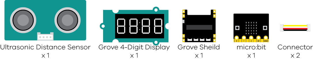
How far away? ============= In this activity you will learn how to use an Ultrasonic Distance Sensor with a 4-digit display
Collect the parts you will need;
Step 2 - Connect Wires
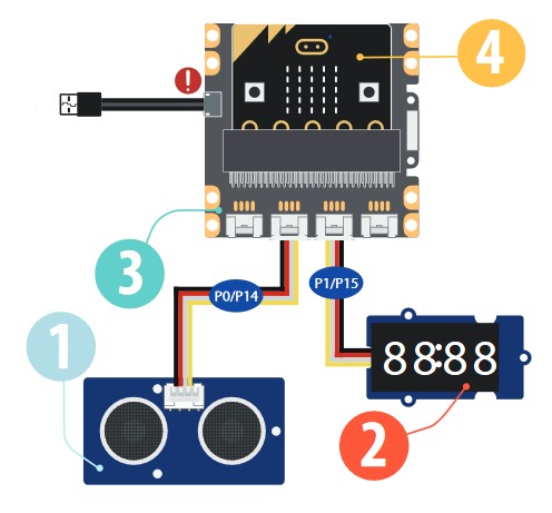
Physical Connection ——————-
- Plug the microbit into the Shield
- Plug the Ultrasonic Sensor into the P0 pin
- Plug the 4-digitDisplay into the P1 pin
Step 3 - Program
Coding: Setup the display
——————
Place a ||grove:Set 4Digit to Display|| block inside a ||basic:On Start||
Set the pins to ||grove:P1|| and ||grove:P15||
let _4Digit = grove.createDisplay(DigitalPin.P1, DigitalPin.P15)
This tells the microbit how to work with the display
Step 4 - Initial Setup
Coding: First Display
——————
Just like before, insert a ||grove:4Digit show number|| after the ||grove:Set 4Digit to Display||
This will show a 0 on the display and show it is connected correctly.
let _4Digit: grove.TM1637 = null
_4Digit = grove.createDisplay(DigitalPin.P1, DigitalPin.P15)
_4Digit.show(0)
The 0 will appear on the display once you download the code.
Step 5 - Display Change
Coding: Change the Display Preparation
——————
Place a ||basic:Forever|| block and insert a ||grove:4Digit show number||
This prepares the display for the ultrasonic distance in the next step
let _4Digit: grove.TM1637 = null
_4Digit = grove.createDisplay(DigitalPin.P0, DigitalPin.P14)
_4Digit.show(0)
basic.forever(function () {
    _4Digit.show(0)
})
Step 6 - Ultrasonic Distance
Coding: Ultrasonic Distance
——————
Replace the “0” in the ||grove:4Digit show number|| with a ||grove:(V2)Ultrasonic Sensor in (cm) at 'PO'|| block
Change the “P0” to be “P1” to match
let _4Digit: grove.TM1637 = null
_4Digit = grove.createDisplay(DigitalPin.P0, DigitalPin.P14)
_4Digit.show(0)
basic.forever(function () {
    _4Digit.show(grove.measureInCentimetersV2(DigitalPin.P0))
})
Step 7 - Download Program
Download & Test
——————–
Click |Download| to transfer your code
The 4Digit Display will show how far away something is from the ultrasonic sensor
===================================================================================================
Activity 9 - Servo Motor
Step 1 - Collect Parts @unplugged
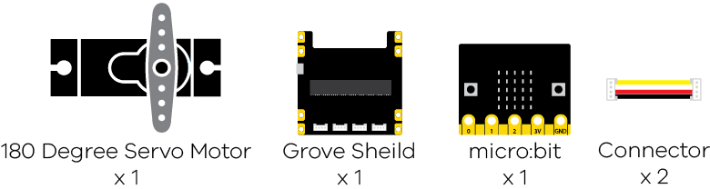
How far away? ============= In this activity you will learn how to make a servo motor move
Collect the parts you will need;
Step 2 - Connect Wires
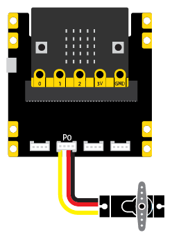
Physical Connection ——————-
- Plug the microbit into the Shield
- Plug the 180 Degree Servo Motor into the P0 pin
Step 3 - Program
Coding: Setup the first position
——————
Place a ||pins:servo write pin|| block inside a ||input:On Button A Pressed||
Set the number “180” to “0”
input.onButtonPressed(Button.A, function () {
    pins.servoWritePin(AnalogPin.P0, 20)
})
Step 4 - Program
Coding: Setup the Second position
——————
Place another ||pins:servo write pin|| block inside another ||input:On Button A Pressed||
Change the Button A to Button B Pressed
Set the number to “180”
input.onButtonPressed(Button.B, function () {
    pins.servoWritePin(AnalogPin.P0, 180)
})
input.onButtonPressed(Button.A, function () {
    pins.servoWritePin(AnalogPin.P0, 0)
})
Step 5 - Test in the simulator
Testing: Does the simulator microbit and servo move —————— In the simulator on the left, press the Button A and Button B on the microbit Does the servo on the screen move?
Step 7 - Download Program
Download & Test
——————–
Click |Download| to transfer your code
If it doesn’t move correctly try reducing the range the servo is moving, so instead of 0 to 180, try 20 to 160.
===================================================================================================
Activity Challenge
Challenge Time @unplugged
Challenge Time =========== Now that you have completed the tutorials here are few challenges you can try Markup :
- The light gets brighter the darker it is
- An alarm sounds if something gets too close
Final Warning
Step END @unplugged
We have added the Grove Extension for you in this tutorial.
You will need to add it yourself by…
Grove=github:seeed-studio/pxt-grove